No products in the cart.
Payment methods accepted
Unsure what Ethernet cable you need?
Look no further than our Ethernet Cable Finder. Answer a couple of questions and let trueBOT guide you to the perfect cable for any situation.
Still have questions? Check out our in-depth blogs, insightful white papers, and instructional videos on all things Ethernet cable and low voltage supplies.

Read: The Difference Between Cat6 vs Cat6A Ethernet Cable

Understand: Selecting the Correct Outdoor Ethernet Cable
Time to find coaxial cable and connectors for your install? Well, you are in the right spot!Check out our in-depth blogs, white papers, and instructional videos about everything going on in the low voltage industry and one of the best sources for coaxial information.
Have questions? Our networking experts have the answers!Check out our Cable Academy. for more information.
Read: The Difference Between Dual Shield vs Quad Shield Coaxial Cable
Understand: How To: Universal RG6 Compression F Connector on Quad Shield Coaxial Cable
Fiber Optic expertise at your fingertips.
Looking to deepen your understanding of fiber optic technology? Look no further than trueCABLE's Cable Academy. Our extensive collection of blogs, masterfully crafted by industry experts, offers a wealth of invaluable insights into the world of fiber optic cabling.
Have questions? Our networking experts have the answers.Check out our Cable Academy. for more information.
Read: Fiber Optic Splicing: Examining the Factors that Affect Splice Performance
Understand: Using Fiber Optics to Extend Your Ethernet Network Beyond Copper's Limits
Effortless cable management. Learn how we do it.
Low-voltage tools and accessories should keep your networking installations clean and organized. trueCABLE has a variety of high quality cable management tools, accessories and informative blogs for all your installation needs.
Check out our Cable Academy today and expand your knowledge.
Read: Copper Fabric Strips for Bonding Shielded Ethernet Cable
Understand: When Aliens Attack! Avoiding Ethernet Alien Crosstalk

Written by Don Schultz, trueCABLE Senior Technical Advisor, Fluke Networks Copper/Fiber CCTT, BICSI INST1, INSTC, INSTF Certified
Bonding and grounding. Of all the subjects that come up when installing Ethernet cable, this one has to be at the top of the list of the items that cause confusion and stress among network cabling installers. It actually is not that complicated when you understand the basic concepts and the differences in terms that are often tossed about. In this blog we will cover these questions and more:
Further, we will cover a relatively simple commercial bonding and grounding environment with a video. The basics will be covered along with some best practices. Lots of pictures will be provided. A few product recommendations and tips will be provided along the way!
This short video will give an overview of the example system we discuss below in detail. It is designed as a visual and audio aid to supplement this written blog:
Before we begin with our discussion, there are some warnings and disclaimers to cover.

Bonding the infrastructure for a telecommunication system (telecom) can be achieved in numerous ways, such as copper wire, metallic conduit, busbars, cold water pipes, ladder rack, cable tray, and structural steel. The bonding infrastructure for telecommunication systems is not designed to serve as the intentional path for ground fault currents or other AC electrical system malfunctions! That is the job of the AC electrical system installed by electricians.
Example of bonding an Ethernet cable shield to the connection hardware:

Grounding is also referred to as “earthing”. They mean the same thing. Conceptually, grounding is to establish a zero (0) volt reference potential to earth. The ground is between the earth itself and the electrical system inside the building. Its purpose is to provide an intentional path for fault current, and provide a path for ESD to drain off to. The idea is to equalize the earth’s potential with the electrical system potential, and all equipment or enclosures that are part of that system.
Ground rods (called ground electrodes) and GECs (Ground Electrode Conductors) are used for this purpose. There are quite a few ways of installing grounding electrodes and wiring up the associated conductors. The types and ways of installing ground electrodes also vary greatly. Here are some factors that influence whether you have a single ground electrode (rod, plate, etc.) or several all bonded together:
It should be noted that grounding without proper bonding is similarly useless.

Simple two-rod grounding electrode system with bonding jumper and GEC. The GEC connects to the main AC electrical panel in this case. Image courtesy of BICSI.
Installation of communications cable (Ethernet included) requires an infrastructure of some kind. In a commercial facility this is likely to be:
Without the above infrastructure, you would have a hard time installing a large amount of Ethernet cable in an organized way!
Given that it is not structurally sound nor safe to use plastic like PVC in a commercial building for supporting all of your cable, ferrous metal (steel) is used instead. Obviously, steel can conduct electricity.
So, bonding to ground the telecommunications system needs to be done for:
The purpose is to ensure human safety and reliability of the telecommunication system by equalizing it all and pathing it to ground. Consider this undesirable situation:
You also want your cable shields for any shielded cable to function properly. Without a bond to ground, shielded cable won’t be shielded any longer and can actually cause a problem with data transmission.
What gets bonded to ground in a telecommunications infrastructure?
*This includes conduits more than 3 feet in length and anything metal that you installed to support or organize your cable except small items like J-hooks.
Who is responsible for the telecommunications bonding infrastructure? You are, as the installer. The electricians should have already designed and installed an AC electrical system that you will eventually bond to. All of your bonding work will lead back to the PBB or Primary busbar, traditionally in the EF or Entrance Facility. Now, we start with some definitions because engineers just love acronyms for everything.
In larger telecommunications bonding and grounding systems you see terms like:


Example of a PBB (also called main busbar). Image courtesy of Harger.

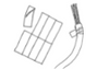
Example of a SBB. Note the bond connection in the third from left position that bonds the ladder rack to the SBB.

2” standoff with insulators must be used on the PBB or SBB. Image courtesy of BICSI.

Rack busbar or RBB. Note the bonding conductor that bonds the rack metal to the RBB. The RBB is bonded back to the SBB.

Multiple examples of rack bonding. The first example shows rack bonding without a RBB. The last two examples show horizontal or vertical busbars. Image courtesy of BICSI.
** Some telecommunication equipment does not require, nor has an attachment point for, a bonding conductor. In this case it is acceptable to rely upon the power cord. This includes rack mounted equipment in addition to non rack mount equipment.
Ok, so now that you are familiar with the basic terms let’s see some diagrams:

Placement of the TBC. Remember, only a registered and qualified electrician should make the connection from the PBB or any SBB to the AC electrical system! Image courtesy of BICSI.

Small system example. Image courtesy of BICSI.

Large system example. This is a multi-story building. Image courtesy of BICSI.
Using the correct hardware to make the actual connection that establishes an electrical bond is critical. All hardware must be recognized by a NRTL (Nationally Recognized Testing Laboratory)--preferably UL. Here are acceptable physical connection methods:

Two hole compression lug. These are most commonly used. Image courtesy of Harger.
When attaching a listed two hole lug to a busbar, use a conductive anti-oxidation grease to prevent corrosion. Thinly spread the grease on the busbar mating surface with a brush. Mating surfaces should be free of oxidation or other contaminants.

Image courtesy of Amazon.
Prior to grease application, mating surfaces like busbars can be polished with a green synthetic “scotch” pad. Paint MUST be removed from the bonding surface on rack hardware, rack framing, ladder racks, etc. A wire wheel attachment on a hand drill is ideal for this. Use eye protection!
For plain end metallic conduit used for communications cable over 3 feet long, use screw on or bolt on split collars that have plastic protective sleeves to protect your cable from damage.

Bolt on split collar for conduit. Image courtesy of Harger.

Installed example of a split collar, bonded to the conduit and back to the SBB
If available in the TR or ER, bonds shall be made to:
That said, never assume that structural steel or cold water pipes have a low resistance path to ground. Two-point resistance testing will have to be performed to be certain it is an effective bond. This becomes critical if the structural steel serves as multiple primary bond points or even takes the place of the TBB. The resistance value must be 0.1 Ω (100 milliohms) or less.
Bonds at the busbar should have a minimum 8” inside bend radius. 10” inside bend radius is preferred. A 90° angle should also be installed as shown.

Bend radius and angle for bonding conductors. Image courtesy of BICSI.
Bonding conductors may need to be sized for length. Per BICSI if no bonding conductor in the telecommunications installation exceeds 100ft then 6 AWG is adequate to equalize all potentials in the cabling system. If bond conductors exceed 100ft then sizing for length will become necessary. TIA has a slightly different take on the matter, and actually gives a table of sizing for length when it comes to the TBB or BBC:

So, who is more correct? I tend to follow the BICSI recommendation of 6 AWG up to 100ft unless there is some reason I should do something differently. I typically use this chart to gauge the TBC (the conductor from the PBB to the AC electrical system ground).
Yes. Entire books, actually. The better question is what are rules you have to follow and what are best practices that are not necessarily law?
The National Electric Code, which is part of the National Fire Protection Act part 70, sets out guidelines for residential and commercial electrical safety and covers bonding and grounding in detail. Secondarily, bonding and grounding is also part of a standard as set by ANSI/TIA 607-D. Furthermore, BICSI (Building Industry Consulting Service International) has classes and study materials aimed at bonding and grounding best practices. The BICSI guidance is largely based upon the NEC/NFPA 70 and ANSI/TIA 607-D but they do add their own methods and best practices to make this whole subject quite understandable. I strongly recommend the BICSI Installer 1 and Installer 2 series of courses in addition to their specialized bonding and grounding courses.
So, which part of these items should you follow and what is actually law? First, laws are set by local codes. It is entirely possible (but unlikely) that none of these guidelines or standards is actually law in your area. It is also entirely possible that all of the guidelines in the NEC were adopted directly into local law without change by your municipality (very likely). Finally, your local area may have stricter codes than the NEC guidelines and ANSI/TIA standard. You will have to research to find out. Contacting a local code inspector is not a bad idea. It is better to speak and get advice ahead of time rather than risk making a mistake that will get an occupancy permit denied or delayed.
So, there you have it! Commercial bonding and grounding, in depth. Not all topics were covered here. This blog is designed to acquaint you with the topic but is not by any means exhaustive. With that, I will say…
HAPPY NETWORKING!!
trueCABLE presents the information on our website, including the “Cable Academy” blog and live chat support, as a service to our customers and other visitors to our website subject to our website terms and conditions. While the information on this website is about data networking and electrical issues, it is not professional advice and any reliance on such material is at your own risk.