


How Many Fiber Connections Are Too Many: Calculating Fiber Link Loss Budgets
Written by Ben Hamlitsch, trueCABLE Technical and Product Innovation Manager RCDD, FOI
Engineering a fiber optic network is a delicate balance. As with any system, you need to identify criteria for performance and then determine how to achieve those requirements. It’s vital to remember that we are talking about a system that is the sum of its components. The fiber link budget is crucial to a fiber optic system; it refers to the amount of loss that a fiber cable plant should have. Using the methodology described in this article, we can calculate the budget for a fiber link.
Methods for calculating the link budget of a given fiber optic link system can be approached from a variety of angles. In order to get the most reliable results, an Optical Time Domain Reflectometer (OTDR) trace of the actual fiber connection should be completed. This will provide you with the real loss numbers for all events (connectors, splices, and fiber loss) in the link. In the absence of a genuine OTDR trace, there are two options that may be utilized to estimate the link budget.
Installing fiber optic cables properly requires precise measurement and testing to guarantee optimal network performance. Transmission reliability might be compromised if there is excessive signal loss in the optical cable. How can we calculate the cost of fiber link losses? Keep reading, and you'll learn how to evaluate the performance of a fiber link and determine how much light is being lost in the process.
Characteristics of Optical Fiber Losses
What exactly is the loss of an optical fiber? Fiber optic attenuation, also known as attenuation loss, is the reduction in signal strength between an input and an output due to losses in the fiber cable. The attenuation loss of a fiber cable can be caused by a number of different things, including the material's inherent absorption, bending loss (both macro and micro), fiber connection losses, and splice loss.
Optical fiber losses may be broken down into two classes: those produced by the fiber's inherent characteristics and those induced by environmental and operational factors. Absorption loss, dispersion loss, and scattering loss due to structural imperfections make up what is collectively referred to as "intrinsic optical fiber losses." Splicing loss, connection loss, and bending loss are all examples of “extrinsic optical fiber losses."
Standards for Fiber Loss
TIA/EIA standards are developed by the Telecommunications Industry Association (TIA) and the Electronic Industries Alliance (EIA), respectively, and are widely accepted and used in the optical fiber industry. They specify performance and transmission requirements for fiber optic cables, connectors, etc. The attenuation coefficient of fiber optic cable is given in decibels per kilometer, and this is the value that gives the allowable loss for the overall fiber cable. When calculating fiber loss, this is a crucial factor to consider. Below is a graph depicting the maximum attenuation and minimum transmission capacity for several fiber optic cable types, as specified by TIA/EIA-568.

How Can You Determine the Amount of Loss in an Optical Fiber Link? Tier 1 Testing
An Optical Loss Test Set (OLTS) is considered a power meter/source Tier 1 tester. This is used to test the loss across a given cable link from end to end. The following computation has to be carried out to determine whether or not the connection functions appropriately. During the process of installing an optical cable, it is necessary to do a calculation to determine the maximum signal loss that may occur across a particular fiber link. To begin, you need to be familiar with the formula for fiber loss, which is as follows:
The Total Link Loss = Cable Attenuation + Connector Loss + Splice Loss
Cable Attenuation (dB) = Maximum Cable Attenuation Coefficient (dB/km) × Length (km)
Connector Loss (dB) = Number of Connector Pairs × Connector Loss Allowance (dB)
Splice Loss (dB) = Number of Splices × Splice Loss Allowance (dB)
It is important to highlight that the total loss estimated in this manner is only an estimate that makes assumptions about the probable values of the component losses. As a result, the real loss might be higher or lower, depending on various circumstances.
Let's use a real-world scenario as an illustration to walk through the steps of the computation. A multimode 50um fiber optic cable with a distance of 1 kilometer and an optical wavelength of 850 nanometers has been laid between two buildings. The optical wavelength of this cable is 850 nanometers. The cable contains two pairs of LC connectors and one splice.

Let's find the attenuation loss of the fiber cable. Based on the chart above, the loss of 1 km of fiber over an 850nm MM 50um optical fiber cable is 3.0dB/km. This means that the total cable loss is 3.0dB/km 1 km = 3.0dB.
Next, we can calculate the loss of each connector. The TIA/EIA's loss per pair is 0.75dB. Multiply that by two to get the total connector loss, which is 1.5dB. In real-world calculations, the actual connector loss can be found in the specifications for the fiber optic cable from the supplier. This loss value of 0.75dB is the maximum allowable loss for that mated pair.
Finally, we can add up the total amount of splice loss. Use the TIA/EIA maximum loss of 0.3dB per splice, which means that the total loss of a splice is 0.3dB. In the example above, we have a total of one splice, so our splice loss total is 0.3dB.
If there are other parts, like attenuators, etc., you can look for the maximum allowable loss for these and add them to the overall budget to figure out how much loss they create.
When you add up the loss from the cable, the connectors, the splice, and/or any additional parts, you get the total link loss budget. This link has a total loss of 4.8dB, which is 3.0dB plus 1.5dB plus 0.3dB.
Note, that these are estimates based on the allowable loss provided by the TIA/EIA standards.
The loss limits set forth by the TIA/EIA are generally much more forgiving than the actual loss of the cable, connectors, and splices. As an example, your link may have a loss limit of 0.75 dB per mated pair, per the standard. However, your actual loss for that mated pair could be way under that number or way over depending on the quality of the connection and a lot of other installation factors.
There is another way of testing your fiber link (a more accurate and precise way to narrow down your losses to the connector and splice individually), by using an OTDR trace and taking a measurement of the actual link under test, including all the components of that link.
What is an OTDR and how is it used?
Fiber optic cable quality may be checked with an OTDR. The OTDR is a high-powered laser transmitter that delivers a light pulse along the fiber. The OTDR's front end features a coupler that channels reflected and backscattered light to a sensitive receiver. It has the ability to detect defects, measure length, and validate splice and connector loss. An OTDR may also be used to take a "photo" or snapshot of a freshly laid fiber optic cable. If issues develop in the future, the original trace can be compared to a new one. Having the original OTDR trace paperwork from when the cable was placed is usually helpful for analyzing the OTDR trace.
If you need to test a cable plant with splices or a lengthy cable (more than around 250 meters, or 800 feet), an OTDR is your best bet. The information gleaned from an OTDR's data is generally shown in the form of a "trace" or "signature" that may be saved for later use or compared to a blueprint in the event of network difficulty. The insertion loss of a fiber optic cable is more accurately measured using a test source and power meter than with an OTDR. The only thing OTDRs do is verify the integrity of the fibers, connectors, and splices and point out where the cables end. Naturally, OTDR traces are also put to use in troubleshooting, since they reveal the locations of fiber breakage when compared to the installation information.
The OTDR works by sending out a high-power pulse and tracking the light's return over time. The OTDR detects light at any given time as a result of the pulse's dispersed light as it travels through a section of the fiber. The index of refraction of the fiber optic glass in the fiber's core can be used to calibrate the speed of the pulse as it travels down the fiber. The OTDR can use what it sees in the backscattered light to pinpoint an exact spot in the fiber. This means that the amount of backscattered light at any given location along the fiber's length may be seen.
Thankfully, there are extremely smart engineers to take the complicated math out of the equation, and the fiber technician just needs to understand how to read the OTDR trance. Because of the logarithmic nature of power loss, it is important to note that the reported values are shown in decibels (dB).
So how does it work? The amount of light reflected back to the OTDR is dependent on the length of the outgoing test pulse, the peak strength of the OTDR test pulse, and the backscatter of the fiber. You can send out additional pulses and average the returning signals to receive more backscattered light if you need it for more accurate readings.
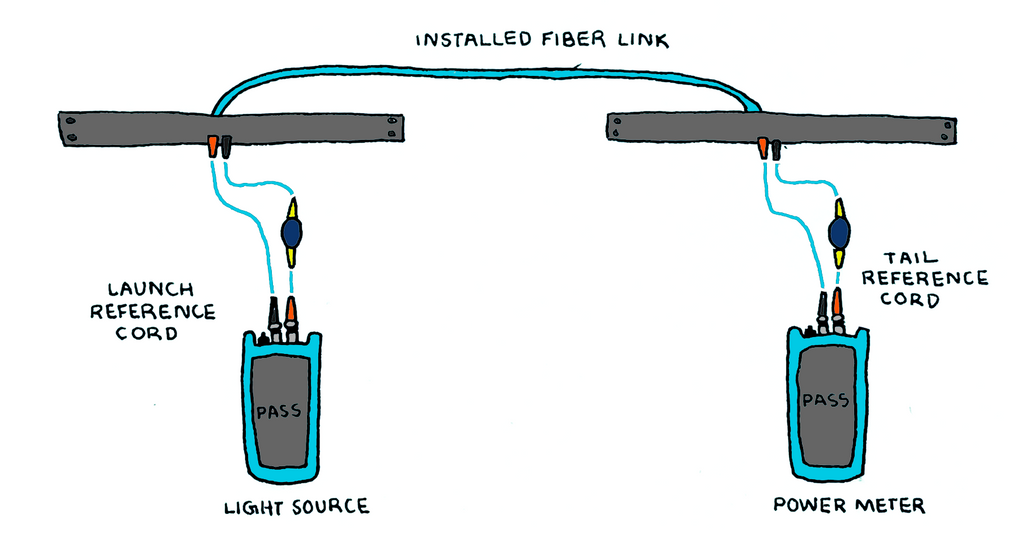
A launch cable and perhaps a receive cable are required for the operation of an OTDR. The launch cable offers a reference connector for the first connector on the cable under test and allows the OTDR to settle down or stabilize after sending the test pulse into the fiber. In order to take measurements of the connection at the end of the cable under examination, a receive cable is employed at the far end. This process can be seen in the example below:

An OTDR, which is considered a Tier 2 tester, is different from an OLTS power meter/source Tier 1 tester in the type of information it delivers and the information it provides to the user. In the case of the OLTS power meter/source, the overall link is tested end to end against a specified loss budget. As we discussed earlier in this article, the fiber link may consist of two fiber connectors, a splice, and the fiber optic cable itself. The OLTS test gives a pass/fail based on the given loss budget for the end-to-end fiber link.
An OTDR allows for a much more granular option. Where an OTDR will shine is when there is an issue with that cable link that has just been tested by the OLTS power meter/source and the link has failed. The OTDR can answer these questions... Why did the link fail? Where in the link is there an issue…at the connector or at the splice? Is there an issue with the fiber cable itself? The OTDR will measure the insertion loss as well as the reflectance loss for each of the events along the cable link. These important troubleshooting questions can be answered and pinpointed to a specific, precise location for the cable link under test.
Typically, the normal fiber cable link will have connectors on both ends of the cable. Additionally, there may be a splice point or two along that same cable link. What is most important is that the link under test is able to pass the specified cable link loss budget and that whatever optics are used to send the data from point A to point Z, there is enough power from the VCSEL or laser to do so. Different applications and lengths of cables will require different active electronics to get the data successfully over the fiber cable.
Loss budgets should always have some wiggle room; it's better to error on the side of caution and leave yourself some breathing room, especially if you plan on using field termination or splicing, which can introduce loss-inducing installation variables like air gaps or misaligned fiber cores. It's also important to account for buffer space in the cable plant in case of last-minute changes, repairs, or deterioration of splices. Keep in mind that the test reference cables will mate with the connectors at both ends of the channel, so you'll need to account for their loss in the loss budget.
Several types of fiber have different maximum distance requirements that are outlined in the various fiber application standards. And therefore, you still need to stay short of the length restrictions for a certain application even if you're well under the loss restrictions.
By doing Tier 1 testing on the channel after installation with an optical loss test kit, you can be sure that the insertion loss is within the loss budget. And if there are any issues, an OTDR can be a good troubleshooting tool. It is important to constantly compare your loss budgeting calculations from the design phase to the outcomes of your tests to ensure your system is within the loss budget and you are able to maintain your accuracy.
HAPPY NETWORKING!
trueCABLE presents the information on our website, including the “Cable Academy” blog and live chat support, as a service to our customers and other visitors to our website subject to our website terms and conditions. While the information on this website is about data networking and electrical issues, it is not professional advice and any reliance on such material is at your own risk.


