No products in the cart.
Payment methods accepted
Unsure what Ethernet cable you need?
Look no further than our Ethernet Cable Finder. Answer a couple of questions and let trueBOT guide you to the perfect cable for any situation.
Still have questions? Check out our in-depth blogs, insightful white papers, and instructional videos on all things Ethernet cable and low voltage supplies.
Read: The Difference Between Cat6 vs Cat6A Ethernet Cable

Understand: Selecting the Correct Outdoor Ethernet Cable
Time to find coaxial cable and connectors for your install? Well, you are in the right spot!Check out our in-depth blogs, white papers, and instructional videos about everything going on in the low voltage industry and one of the best sources for coaxial information.
Have questions? Our networking experts have the answers!Check out our Cable Academy. for more information.

Read: The Difference Between Dual Shield vs Quad Shield Coaxial Cable
Understand: How To: Universal RG6 Compression F Connector on Quad Shield Coaxial Cable
Fiber Optic expertise at your fingertips.
Looking to deepen your understanding of fiber optic technology? Look no further than trueCABLE's Cable Academy. Our extensive collection of blogs, masterfully crafted by industry experts, offers a wealth of invaluable insights into the world of fiber optic cabling.
Have questions? Our networking experts have the answers.Check out our Cable Academy. for more information.
Read: Fiber Optic Splicing: Examining the Factors that Affect Splice Performance
Understand: Using Fiber Optics to Extend Your Ethernet Network Beyond Copper's Limits
Effortless cable management. Learn how we do it.
Low-voltage tools and accessories should keep your networking installations clean and organized. trueCABLE has a variety of high quality cable management tools, accessories and informative blogs for all your installation needs.
Check out our Cable Academy today and expand your knowledge.
Read: Copper Fabric Strips for Bonding Shielded Ethernet Cable
Understand: When Aliens Attack! Avoiding Ethernet Alien Crosstalk
Written by Don Schultz, trueCABLE Senior Technical Advisor, Fluke Networks Copper/Fiber CCTT, BICSI INST1, INSTC, INSTF Certified
Let me tell you about a recent experience I had…
I did a favor for a friend. I would like to think that we all do that. Especially if you are skilled in a certain very technical area, like Ethernet and networking installations, for example. So, I ran our trueCABLE Cat6 Unshielded Riser cable into a couple of wall jacks. I used my friend’s basement as the ideal place to string the cable before they came up into the walls to meet the jacks. This was a simple install for me, easy peasy. I hooked up patch cables from the wall jacks in his living room to his router. Then I used patch cables from the wall jacks in remote locations to hook up Ethernet switches, so that multiple devices in the same remote room could take advantage of a wired connection.
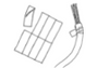
This is what I was trying to accomplish:

Everything was working well until I tried to set up his printer on the network. I spent an hour spinning my wheels. I finally figured out that I had accidentally plugged a patch cable from the wall jack directly into his PC rather than into the little remote bedroom switch. Both ends of the patch cable were connected to the same switch. Everything looked OK at first because his PC had connectivity. Only the printer didn’t. Of course not, the little switch was not connected to the wall jack and was effectively connected to itself, which obviously won’t work...
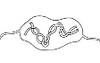
This is what I ended up doing:

Doh! I made a common mistake. I was not paying attention to where I was plugging the patch cables into. I had to stop and think to get back to the basics. At first, it did not occur to me that the printer was not at fault, or I had made one of the most basic mistakes you can make. I am a Fluke Networks Certified Technician after all! I’m immune to these sorts of beginner mistakes, right?
Wrong.
So, this got me thinking. If an experienced installer can make such a basic error and make himself look foolish, then it behooves me to bring everyone (including myself) back to the basics. Amazingly, 98% of the time it is not the cables or networking hardware that is at fault...it is the installer.
If you are not sure about your networking skills, sit down and diagram out how things should be plugged in, so that logically they make sense. Example: a switch cannot communicate with a router unless it is somehow plugged into the router!
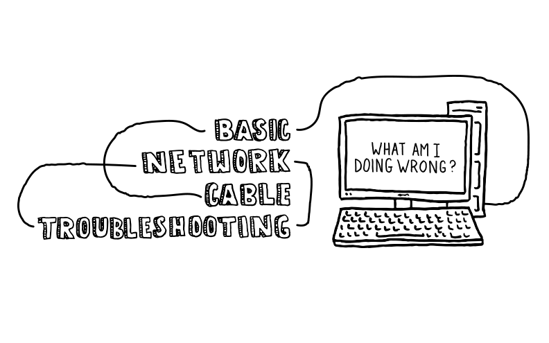
This flowchart is designed to help you identify physical issues in your Ethernet network. If your issues are related to how your router is programmed, then you just stepped into advanced network troubleshooting which can and will get complicated very fast. If that is the spot you are in, then get experienced help.
First up, here are some helpful tools to give you an advantage:

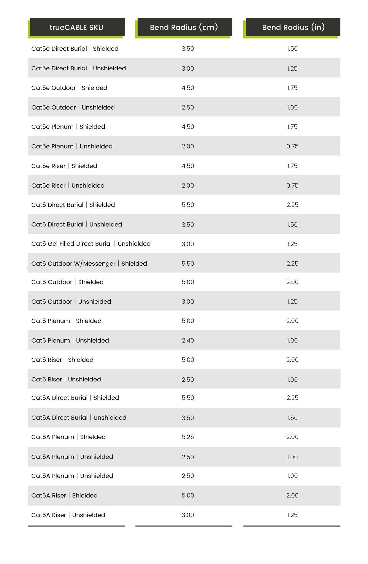
See the blog Obey the Bend, Calculating Wire Bend Radius for additional, more generic, information.
To make this easier to work with, assume the wire is bent into a “U” shape. The distance between the top of the “U” is the bend diameter. Divide this in half for the bend radius. The figures given below are for bend radius.
This diagram gives both color code patterns. Both ends of your cable should be either “A” or “B”, but not both. In other words, pick A or B and stick with it. One is not better than the other.
See the blog T568a vs T568b, Which to Use for additional, more generic, information.

There you are! This blog will help with your basic Ethernet network cable troubleshooting, but remember that we are always here to help too. Please feel free to reach out to our Wire Experts at info@truecable.com and we will go above and beyond to get you up and running. Happy Networking!
trueCABLE presents the information on our website, including the “Cable Academy” blog and live chat support, as a service to our customers and other visitors to our website subject to our website terms and conditions. While the information on this website is about data networking and electrical issues, it is not professional advice and any reliance on such material is at your own risk.