


How To: Terminating a Standard RJ45 Onto Cat6A Direct Burial Unshielded Ethernet
Written by Don Schultz, trueCABLE Senior Technical Advisor, Fluke Networks Copper/Fiber CCTT, BICSI INST1, INSTC, INSTF Certified
In the fourth part of this series about terminating Cat6A Unshielded Direct Burial Ethernet cable, we discuss 8P8C modular plugs (aka RJ45 connectors) and how to terminate them onto your Cat6A direct burial Ethernet cable. There are a large number of 8P8C modular plugs on the market, and picking the right one is essential. This blog will discuss the pros and cons of RJ45s, plus provide some RJ45 termination tips.
This blog, broadly speaking, applies to 8P8C termination onto any unshielded solid copper Ethernet cable, regardless of Category. More narrowly, this blog puts focus on thick Cat6A direct burial and outdoor varieties of Ethernet cable, which pose additional installation and termination challenges as compared to their indoor Ethernet counterparts.
Prior to delving into this termination specific blog, it is a good idea to read Everything To Know About Cat6A Unshielded Direct Burial Ethernet Cable first. In that blog general installation considerations, Power over Ethernet (PoE) handling, length rules, and legal implications are thoroughly discussed.
Below is a video demonstrating termination of our Cat6/6A Unshielded Standard RJ45 Plug onto trueCABLE Cat6A Unshielded Direct Burial cable. Please watch this short video and then return here for additional information!
What is a 8P8C Modular Plug (aka RJ45)?
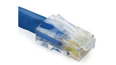
Cat6/6A Standard Unshielded RJ45 (shown terminated to Cat6A Riser Unshielded)
Modular plugs, sometimes referred to as “RJ45”, are actually 8 position / 8 contact (8P8C) terminations designed to accommodate the eight insulated conductor wires found inside Ethernet copper cable. Here are some highlights:
- 8P8C modular plugs do not have a Category rating
- 8P8C modular plugs are essentially a piece of plastic with eight golden contact pins inside and nothing more
- 8P8C modular plugs are standard on the exterior, but differ greatly from each other on the inside in order to accommodate different thicknesses of Ethernet wire
- 8P8C modular plugs come in passthrough and solid nosed standard varieties and some of them stagger the conductor wires
- 8P8C plugs are male connectors designed to plug into a keystone jack, monolithic patch panel, or directly into a piece of equipment like an Ethernet switch or PoE device that requires power and data over the same cable
Where are 8P8C Modular Plugs Used?
Technically speaking, the only time RJ45s should be seen and used is when they are already pre-terminated onto factory made patch cords. Normally, professional structured cabling system (SCS) installers won’t terminate this style of male connector directly to solid copper Ethernet cable. Typically, solid copper Ethernet is terminated to Insulation Displacement Contact (IDC) terminations such as keystone jacks, creating what is known as a permanent link. Then factory made patch cable is used to patch into that permanent link at both ends. When the patch cords are plugged in, this creates the overall channel.
There is, however, a valid use for these pieces of plastic you can hand terminate. The ANSI/TIA 568-2.D standard allows for Modular Plug Terminated Links (MPTL). This style of link is used to directly plug in devices at the remote end for PoE data and power. Essentially, this is a keystone jack to RJ45 plug type of run. The keystone jack end will still require a patch cord to plug into the PoE switch powering everything up.
Cautionary Note for Cat6A and 10Gbps Data Transmission!
Caution is called for, however, as 8P8C (aka RJ45) plugs are the least mechanically stable way to terminate any type of solid copper Ethernet cable--and therefore mechanical stability may translate into electrical instability. Considering Cat6A cable is likely to be driven to 500MHz and 10Gbps, any instability at the termination will present potential packet loss and other maladies such as intermittent PoE issues. It does not matter whether the 8P8C modular plug is “standard” or “passthrough” as the mechanical instability is related to how the conductor wires are held by the fragile contact pins found inside either style modular plug and the potential for lateral movement at the rear entrance of the RJ45 plug housing. Far more detail on this nuanced subject can be found in Terminating Pass-Through RJ45 Connectors onto Solid Copper Ethernet Cable -- A Really Bad Idea?

It is absolutely essential the fitment of the 8P8C modular plug be perfect for the cable in question, and the procedure must be followed precisely to give the maximum possibility of success!

NEVER hand-terminate 8P8C modular plugs onto BOTH ends of solid copper Cat6A Ethernet cable and expect to achieve 10Gbps reliably.
It’s All About the Fitment
When it comes to selecting the right RJ45 connector for our Cat6A Unshielded Direct Burial Ethernet cable, we already know three crucial pieces of information:
- 23AWG Copper solid copper conductors (not stranded) and require 3 prong pins
- Insulated conductor diameter is 1.01mm
- Overall jacket diameter (OD) is 6.80mm
trueCABLE sells a RJ45 8P8C modular plug that is ideal for this cable and application, which is our Cat6/6A Standard RJ45 Connectors|Unshielded. Aside from the fact we are dealing with unshielded Ethernet cable and know we will need an unshielded RJ45 connector, this connector accommodates:
- 0.95 to 1.15mm insulated solid copper conductors
- Up to 7.30mm cable jacket diameters
- Solid copper conductors of 23AWG
So, we have a perfect match as the cable falls right into the middle of the fitment range of the modular plug, which helps greatly when dealing with unexpected manufacturing tolerance variation on the Ethernet cable’s insulated conductors.
In addition, this particular RJ45 8P8C plug is “standard” which means solid nosed. The conductors don’t pass through the front of the connector. A staggered load bar is used to load and organize the conductors to assist in seating the conductors under the golden contact pins.
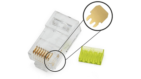
The plug in question, showing 3 pin style golden contacts and the load bar.
One of the nice features of this particular 8P8C RJ45 modular plug is the load bar. It is high visibility green and staggers the conductors. High visibility green is good for usability and really important when you consider the load bar only properly fits ONE WAY into the plug housing. The other important item, that being the stagger pattern, benefits Cat6A performance due to reduction of crosstalk (NEXT) at the connector. Cat6A operating at 10Gbps will require 500MHz bandwidth, and crosstalk reduction is critical. See Load Bar Staggered RJ45 Connectors: Do They Increase Ethernet Cable Performance? where “straight across” and “staggered” designs are tested and compared for performance.
Tools and Materials
- Cat/6A Unshielded Standard RJ45 Connectors
- Cat6A Unshielded Direct Burial Cable
- Cable cut and strip tool
- Micro flush cutters
- RJ45 Crimp and Termination Tool
What special tools are needed for terminating Cat6A direct burial cable? Technically none. This is not a Category specific operation. No special tools aside from those listed above are required.
Cable Stripping and Preparation

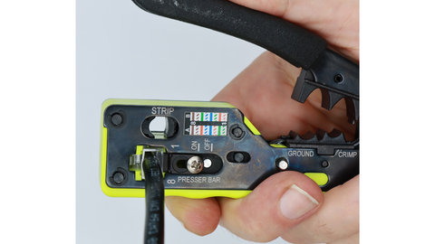
The cut and strip tool and micro flush cutters are critical for cable prep!

Strip off about 1.5” to 2” of cable jacket. You want to score the cable jacket, NOT cut through it! If you accidentally cut through you may have nicked a conductor.
A common question is how long should the cable be stripped prior to termination? Well, that is up to you but trueCABLE recommends at least 1.5” of cable jacket be stripped off to make termination easier.
Another common question we get is what is the recommended strip length for the conductors? None, technically. You don’t strip the conductor wire insulation off prior to termination with Ethernet cable. You only strip off the cable jacket and the terminations bite into and through the plastic insulation of the copper conductors themselves.
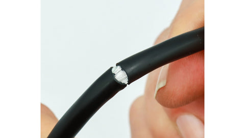
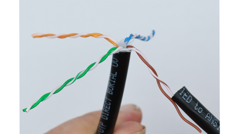
Once the jacket has been scored, break the jacket at the score.
Keep the piece of cable jacket you stripped off. It will come in handy as a tool when untwisting the conductor pairs.

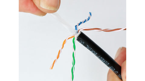
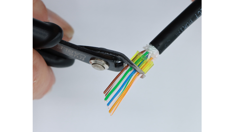
Jacket removed revealing the PE tape, rip cord, and waterblock tape. All need to be removed with the flush cutters right down to the jacket edge.
Removal process with flush cutters. Be careful not to nick any conductors during this process or you will need to start over!
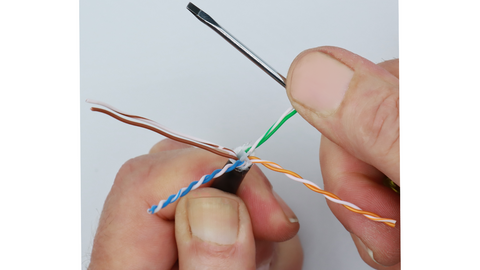
Place the conductors into a “star” pattern, which will expose the spline.

Make four cuts, one on each “wing” of the spline, at a downward angle. Be careful to not nick a conductor wire during this process.
Once the spline wings have been cut, twist the spline to remove.
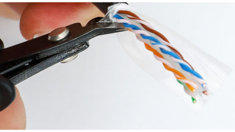
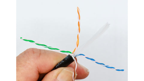
Using that piece of cable jacket you stripped off, untwist the conductor pairs.
Using a smooth metal or plastic shaft, straighten the conductor pairs.
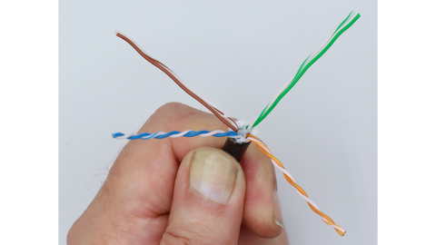
Example of two pairs that have been straightened.

Do not apply too much force when straightening the conductor pairs. You may straighten two at a time as shown. Try and keep the number of passes to three or less, as overworking the conductors can thin out the copper and cause issues.
RJ45 Termination Procedure
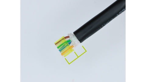
Place the conductors in the correct sequence. T568B is shown. Slide the load bar down the conductors to hold them in place. Note the position of the load bar as it is position sensitive.
Use either the T568A or T568B sequence. Neither one is superior to the other. Testing has shown they perform identically. The main thing is to use the same sequence throughout the project or you will experience data transmission issues!
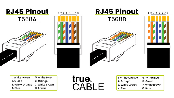
Wiring schematic for your reference.
Once the load bar is seated at the right point, flush cut the conductor wires even with the front of the load bar.
The end of the cable jacket and beginning of the load bar should have approximately 3/16” separation between them and 1/4” maximum.
 DO NOT attempt to set the load bar closer to the jacket in an effort to achieve an unrealistically “tight” termination. The conductor wires place stress on the load bar. A load bar under excessive stress may not seat properly!
trueCABLE has tested cable seating depth and conductor untwist extensively. 0.50” is all that is required. Unrealistically “tight terminations” do not measurably improve performance and only serve to make your job more difficult.
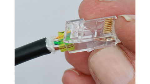
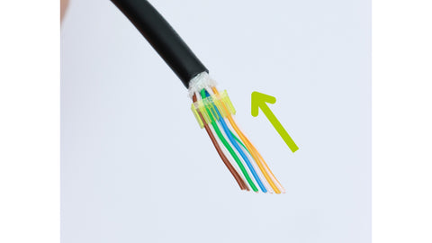
Insert cable and load bar assembly into plug housing. Note orientation of the load bar in relation to the plug housing and conductor colors. This is a T568B termination.
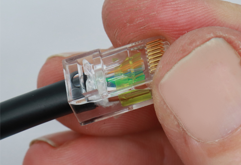
Insertion process continued. Push the load bar until it stops directly under the golden contact pins in the plug housing. The load bar will only seat one way.
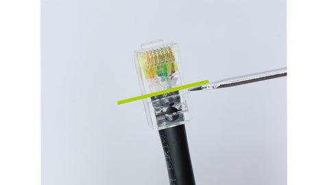
Once fully seated, the cable jacket should stop at the green line shown.
IF THE CABLE JACKET does not seat deep enough to the line, you will need to start over. If the cable jacket is pushed too far in, there is a risk of distorting the plug housing and causing damage.
Insert the RJ45 plug and cable assembly into the All-In-One Crimp & Termination Tool and terminate the golden contacts.
Carefully check your work! See below.
What are some signs of a poor termination that could cause issues?
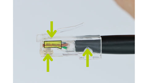
Per the picture above, check the following for a successful termination:
- Strain latch is fully engaged (plastic triangle indenting and holding cable at rear of plug housing
- Golden contacts are fully seated
- Load bar is in the fully seated position as shown (outlined in black)
Your termination is done! Nice work.
Common Questions & Answers
trueCABLE is frequently asked questions about proper 8P8C (aka RJ45) terminations. We have posted the most common ones below.
What additional protection/sealing is recommended for outdoor RJ45 terminations?
By themselves, RJ45 terminations are in no way water or weather resistant. Any moisture that gets inside the plug will ruin the termination. There are two ways around this issue. The first way is the outdoor end-point device itself. All devices meant to be mounted outdoors should provide some protection for the RJ45 termination with a water resistant housing. The second way is to mount a weather proof enclosure and to plug the RJ45 termination into whatever receptacle the device provides inside the enclosure.
How can you test the termination to ensure it was done correctly?
Visual inspection is the first step. Testing performance, however, is a thorny subject. If you possess something like a Fluke DSX-8000 with copper modules then you are set to go and the answer is easy, but very expensive. If you need to Certify your drops, you have no alternative but to purchase (or rent) an expensive field certification device. For all others, there are ways of testing that will get you the answers you seek for less money. Please see Testing 10 Gigabit Ethernet Over Copper on a Shoestring Budget.
What common termination mistakes should I avoid?
Here are the most common mistakes when dealing with RJ45s:
- Shopping by Category (especially when mixing brands of components). RJ45 plugs do not technically have a Category and the Category has no bearing on whether the plug will fit or not.
- Not inserting the cable jacket far enough into the RJ45 plug for the strain latch to engage. This creates a fragile termination that is even more fragile than RJ45 terminations inherently already are. See What Does a Bad Termination Look Like?
- Incorrect wiring sequence. This occurs due to the conductor shifting during insertion into the plug housing or putting the plug on upside down. Only careful inspection of the finished termination, along with wire map testing will real if any issues are present.
So there you have it! Now you are an expert of terminating a standard unshielded 8P8C (aka RJ45) modular plug onto Cat6A Unshielded Direct Burial Ethernet cable. Practice will make perfect. Your workmanship is critical as RJ45s are unforgiving of poor workmanship. Grab some plugs and cable and try out the foregoing process. trueCABLE is always ready to assist if you need help!
HAPPY NETWORKING!
trueCABLE presents the information on our website, including the “Cable Academy” blog and live chat support, as a service to our customers and other visitors to our website subject to our website terms and conditions. While the information on this website is about data networking and electrical issues, it is not professional advice and any reliance on such material is at your own risk.


