


Slaying the Dragon: RJ45 Termination of Cat6 & Cat6A Shielded Direct Burial Ethernet
If you want a challenge when terminating Ethernet cable, then try putting a 8P8C (aka RJ45) connector onto it. If you want to sign up for the ultimate challenge then try putting a RJ45 connector onto shielded direct burial Ethernet! trueCABLE sells three types of shielded direct burial Ethernet:
- Cat5e Shielded Direct Burial (waterblock tape)
- Cat6 Shielded Direct Burial (waterblock tape)
- Cat6A Shielded Direct Burial (waterblock tape)
Of all the cables that trueCABLE sells, the last two cable types in particular will sit there on the spool and just mock you as you do your level best to tame it. You just know it laughs and makes rude gestures behind your back. Up until now, many have found this type of cable to be an exercise in frustration, despite how well suited it is for the task it was designed for. Adding to the frustration was the lack of well-designed RJ45 shielded connectors and the tool to go with those connectors.
 Please note that really thick shielded direct burial cable is best terminated to shielded tool-less keystone jacks or Cat6A Shielded Field Termination Plugs, not RJ45 connectors.
Solid copper Ethernet and RJ45 connectors are a potential recipe for trouble due to various reasons. The thicker and more complex the cable, the more potential there is for trouble. You can read all about that in Terminating Pass-Through RJ45 Connectors onto Solid Copper Ethernet Cable -- A Really Bad Idea? If you do put a RJ45 connector onto solid copper Ethernet cable, don’t do it at both ends. The “switch end” of the cable should still be terminated to a keystone jack.
There are certain situations where you must use a RJ45 connector at one end of your cable. So, we will walk through the process of putting an RJ45 shielded plug onto one of these beastly cables. I will take you through each part of the process step by step and provide all the tips and tricks for this task. Like anything, practice will make perfect, but this will give you an excellent head start and maybe add something to your knowledge base. Note that this process is identical between Cat6 and Cat6A direct burial shielded cables, due to largely similar construction.
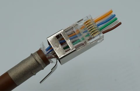
Cat6/6A Shielded Pass-Through RJ45 Connector - In Detail
Being successful with complex Ethernet termination means also being armed with knowledge, not just the right tools. Let’s talk a bit about our Cat6/6A Shielded Pass-Through RJ45 Connector in depth:
- “Ideal” fitment range for insulated conductors is 1.08 to 1.22mm. The “strict” fitment range is 1.05 to 1.25mm, but in practice the ideal fitment range will give best results. The reason is due to variance and tolerances during manufacturing of the plastic coated conductors of the cable.
- Ideal fitment range for cable jacket OD (overall thickness) is between 6.80 and 8.00mm. Ethernet cables thicker than 8.00mm will not fit. Ethernet cables thinner than 6.80mm are not thick enough to permit a secure crimp with the ground collar.
- Uses an external ground collar that serves as a bond point but also as the primary attachment method to the cable. The ground collar is the mechanism that serves as the strain relief!
- By design, the rear half of the plug is entirely metal, so it is easy to bond your cable shield. This means the rear half of the inside of the plug AND the ground collar are all potential bonding points.
- Fits and has been performance tested with all of our Cat6 and Cat6A shielded Ethernet cable (indoor and outdoor)


Tools you will absolutely need are:
- All-In-One Crimp & Termination tool (trueCRIMP)
- Leave the strain latch presser bar set to ON (the tool comes this way from the factory) even though the plug in question does not technically have a strain latch inside.
- Our pass through crimp and termination tool's older model is not compatible with these Cat6/6A Shielded Pass Through RJ45 Connectors. The strain latch presser bar on that tool will crush the rear of your shielded plug.
- Flush cutter
- Cable Stripping & Cutting Tool (optional but recommended-- our All-In-One Crimp and Termination Tool has an excellent cable stripper too but lacks a cable cutter)

Strongly recommended tools and accessories to make your life a lot easier and increase the odds of a good termination:

Our external ground collar crimp tool not only increases the speed of crimping the ground tab, but will greatly increase accuracy of the crimp which is critical to a stable termination. Do not underestimate the usefulness of this tool!

Copper fabric strips allow you to bond the cable shield to your termination hardware without having to deal with folding back the cable shield and increasing cable thickness in the process. Cable shields are fragile and easy to damage prior to termination, all the while getting in your way. The end result is copper fabric strips allow you to increase your speed and will reduce frustration.
Terminations Steps
Pre-step:
Bend the external ground crimp/strain relief collar downward from the default position of 45 degrees to 90 degrees. Bend the tab from the default 45 degree position to a 90 degree position. The idea is to get the collar out of your way.
We will use our trueCRIMP tool to perform the cable jacket stripping for this blog.

- The built-in stripper is self-adjusting
- The size compatibility is 6.00 to 8.00mm cable jacket OD, covering everything from trueCABLE Cat5e Shielded Riser and thicker.
- It helps to roll the cable between your thumb and forefinger to make it more round before stripping. This reduces the chances of nicking a conductor.

Proper score on the jacket. You want a score, not a cut-through.

The properly scored jacket being "popped." Don't toss the stripped off jacket piece just yet. 
Keep that cable jacket piece!

Flush cut the nylon ripcord at the cable jacket edge.

Make a small nip in the cable shield and…


- The copper fabric strip has a conductive adhesive on one side
- The bond is achieved with the conductive adhesive side of the copper fabric strip making contact with the tinned ESD drain wire
- The tinned ESD drain wire is in contact with the cable shield inside the cable
- The last ⅛” of the cable is skipped to allow for easier cable end identification inside the RJ45 plug. More on that later.

Remove the water block tape and other wraps. Remove as much as possible.

Splay conductor pairs into a star pattern.

Remove the spline by making four snips. Rest the clippers on the cable jacket edge and snip each "wing" downwards. Be careful not to nick a conductor. DO NOT remove the spline by cutting straight across--it will make termination more difficult.
The internal spline is found on all trueCABLE Cat6 and Cat6A cables. The purpose is to improve performance by reducing pair to pair crosstalk. We did not add it to make your life difficult!

Twist spline to remove.

Untwist time. You can toss your free tool when done. Check to be sure the conductors are untwisted as much as practical, but not more than necessary. In other words, right down to the cable jacket but no further.
- Cable jacket pieces are ideal for untwisting conductor pairs
- Separate the very end of the conductor pair and use the cable jacket to untwist the pair downward

All conductors untwisted. Now it is time to remove the kinks.
- Use a smooth (preferably chrome plated) metal dowel like a screw driver shaft to remove the kinks from the conductors
- Make two to three passes from the jacket edge to the end of the conductor
- DO NOT use too much pressure. You will thin out the copper conductor and possibly remove the conductor insulation if you use too much pressure.
- After the majority of the kinks are gone, place the conductors into your preferred color sequence (T568A or T568B) and continue working on getting them lined up and straight as possible.


- It is critical to get the conductors straightened out
- The straighter they are, the easier it will be for you to put the connector on


Flush cut the conductors. T568B sequence shown. I like to work from the top down (if I can)—White-orange at the top and solid brown at the bottom. This matches how we will put the plug on.
- You can use either T568A or T568B for your sequence. One is not better than the other. Just be sure to use the same sequence at both ends of the cable unless you want to create a crossover cable.
- Once you have those conductors lined up, keep pressure on them, so they don't get out of order on you. They will trust me. Try it once to see what I mean...
Push the conductors into the plug, so they come out the nose. Don't fully seat the cable yet. The conductors will automatically stagger for you. Recheck the color sequence.
When pushing the conductors into the plug, watch out for that plastic ledge! It is easy to hang up on that point, so your conductors will need to be straight going in.
The plug staggers the conductors because they will not physically fit inside the plug in a standard "8 across" fashion. Conductor insulation thickness is the reason. The staggered design has the side benefit of reducing crosstalk at the connector--especially for Cat6A.

Push the cable into the plug rear and seat the cable to the plastic ledge stop point. The very end of the cable jacket should just show up right after the metal. See picture for stop point.
DO NOT attempt to seat the cable jacket deeper into the plug. Seat to the plastic ledge stop point as shown. Attempting to seat further will distort the plug housing and potentially ruin your termination.


Use a flat blade screwdriver to bend down the tab “wings” and pre-start the collar crimp.

Place the assembly into the “large” collar crimp cavity on the ground crimp tool.

Ensure about 1/16” spacing between the ground collar crimp tool and rear of the plug body and fully collapse the tool handle to complete the crimp.
- Check to see if the ground collar is firmly crimped. If it is not, pass the assembly over to the smaller crimp cavity and lightly squeeze again.
- A proper crimp will mildly compress and indent the cable jacket


Place the assembly into the All-In-One Crimp & Termination tool and fully close the handle to terminate the golden contacts and flush cut the conductors.

Completed crimp and termination!


A mild 1mm under-cut on the tab, caused by the flush cut blade, is NORMAL
All done. We have slayed the dragon! Go plug it in, and HAPPY NETWORKING!
Wait!
Something not right? Your cable not performing your expectations? You could have a bad or poorly terminated RJ45 plug. Better check out What Does a Bad Termination Look Like?
trueCABLE presents the information on our website, including the “Cable Academy” blog and live chat support, as a service to our customers and other visitors to our website subject to our website terms and conditions. While the information on this website is about data networking and electrical issues, it is not professional advice and any reliance on such material is at your own risk.


